During wind turbine testing for University of Michigan's Offshore Wind project team, we realized that the turbine's passive yaw system would only kick in at high wind speeds. We suspected that the nacelle was having high interference with the wind, preventing a large moment from being generated at the tail fin. To figure out which nacelle top design would work better with our tail fin configuration, we ran some CFD simulations using different nacelle designs and measuring the maximum moment around the axis of yaw (the nacelle's tower). We began the experiment by simplifying the current nacelle design (to allow for quicker simulation times), and using this as a baseline to measure against experimental nacelle designs. The nacelle was split in half (to reduce computational times and observe moment caused by one fin), imported into Star CCM+ using a rectangular prism control volume, where it was meshed finely as seen below.
After being meshed, a solver was set up using a steady flow and a k-epsilon turbulence model. The wind was simulated as coming directly towards the nacelle at a speed of 12 m/s. After running the solution for 500 iterations (until residuals converged under 10^-3), a moment report was generated to get a general idea of the moment around the yaw axis for the baseline box-like design.

From the moment report, a baseline value of around 12.32N-cm was recorded. This value was then compared to simulations ran in the exact same manner for two other types of simplified nacelle shapes. The next simplified design consisted of an upward, then downward sloping nacelle top as shown below.
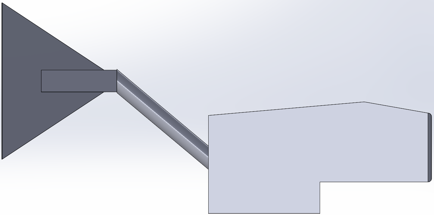
After meshing the model and setting up the solution in the same way as the control design, we generated a moment report to find the moment generated around the yaw axis for an upward then downward sloping nacelle design.
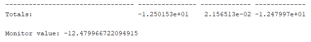
From the moment report, a moment value of around 12.48N-cm was recorded for this design. This design lead to a an increase of around 1.27% in moment generated, likely due to the small surface slope. Finally, these results were compared to a final simplified design consisting of a slightly upward sloped nacelle top as shown below.
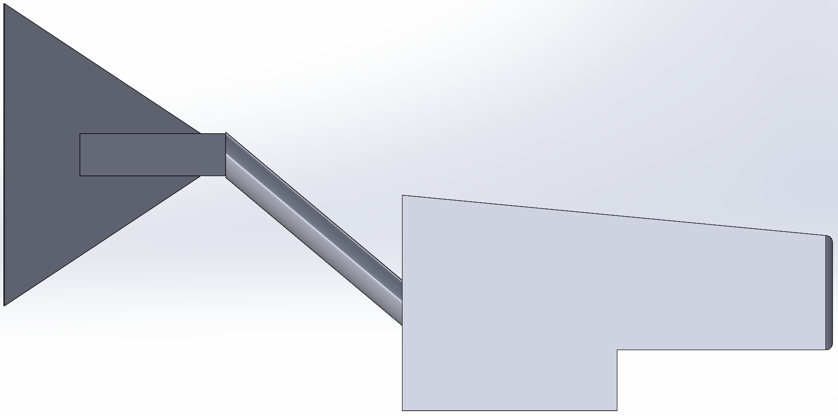
After meshing the model and setting up the solution in the same way as the control design, we generated a moment report to find the moment generated around the yaw axis for an upward sloping nacelle design.
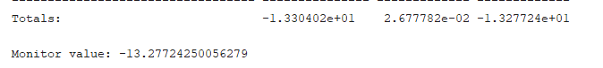
From the moment report, a value of around 13.28N-cm was recorded for this design. This design lead to the greatest increase of around 7.74% in moment generated from the baseline design.
The purpose of this CFD experiment was to understand just how much impact a small design change such as the shape of the nacelle top could have on the turbine's yawing moment. It is unreasonable to expect 100% accurate results in moment calculations coming from CFD, however, it does serve as an extremely useful tool in comparing between different designs to get a rough idea of the impact. This experiment gave us a good idea of a way to allow more yaw moment for our turbine, changing the turbine shape and switching the bearings in the tower should allow us to yaw at much lower wind speeds, making sure our turbine always faces the wind to maximize power output.
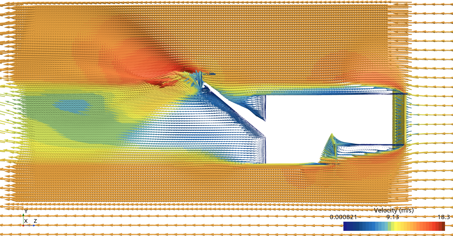
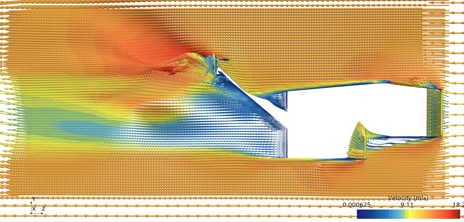
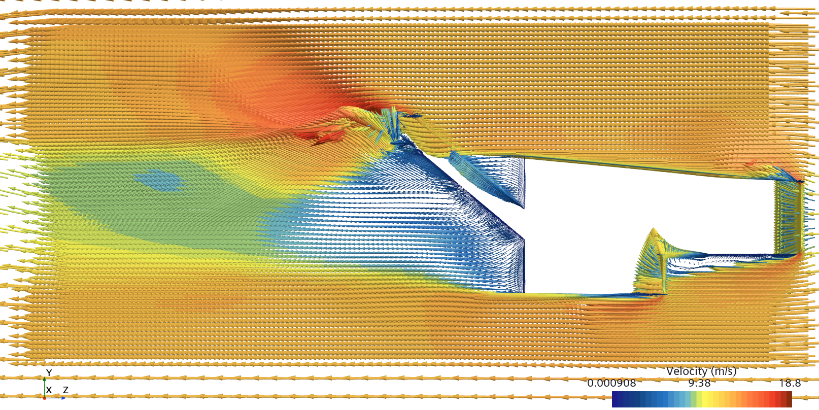
Vector fields from simulations:
Team Members: Timothy Tandean, Alec Jamil