For Design and Manufacturing class (ME 250), my team was tasked with designing and building a remote controlled vehicle that could knock small cubes down from towers and transport them into an elevated basket. After deciding on specific functional requirements, we started sketching out designs that would fulfill these:
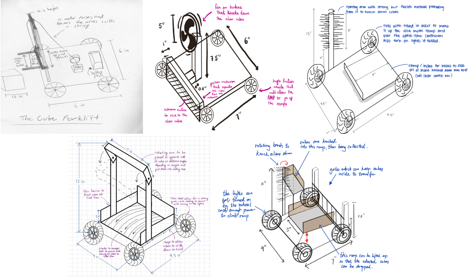
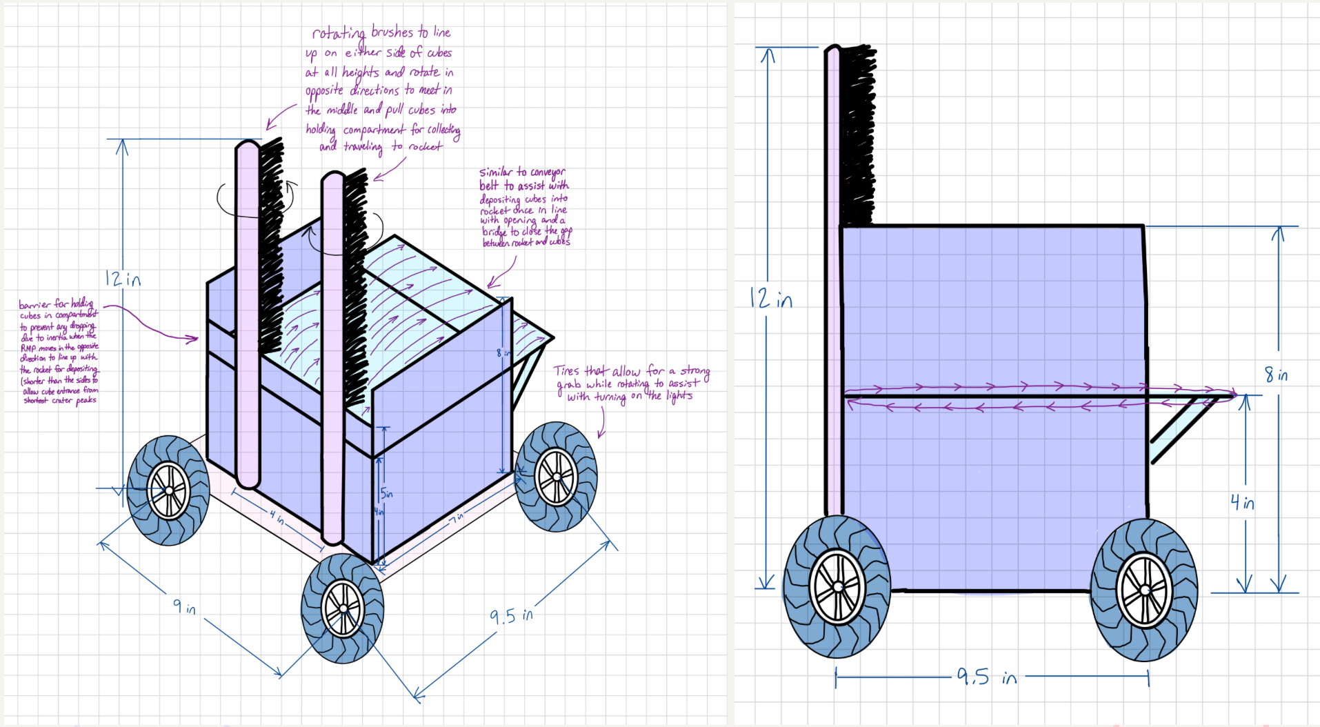
From our design drawings, we combined components and landed at a rough drawing of what our final design would look like:
After landing on a rough drawing, we translated this into a first stage CAD concept using Solidworks:
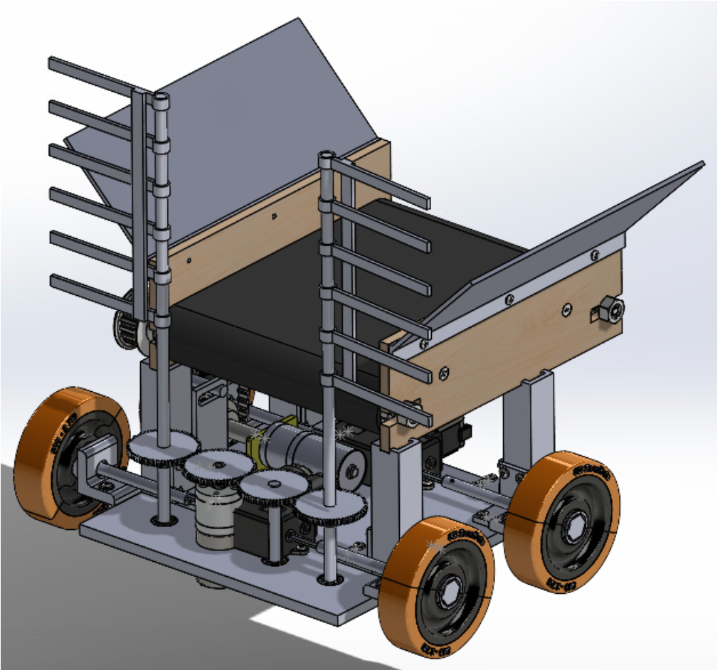
We conducted first principle analyses to decide on the best gear ratio for balancing speed with torque (allowing us to drive up ramps) and we conducted an empirical test of different brush materials based on their stiffness and ability to knock cubes over. The team decided that zip ties were a good fit for our needs. Next, after a design report and meetings with faculty, we modified our design into a near-final CAD version:
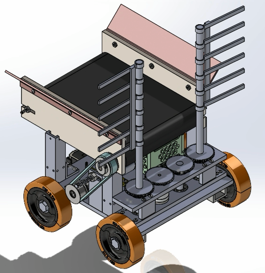
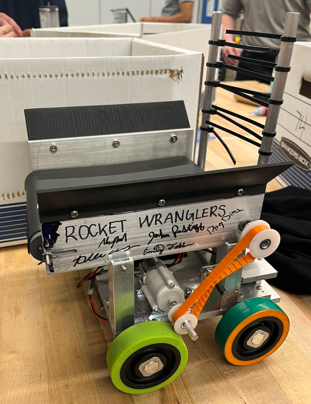
The main changes were making the conveyor side walls out of aluminum so they could be easily water jet and so that we could ream out a hole for a press fit bushing. Additionally, the drive train was changed so that the front two wheels were driven by a double gearbox and the back two were independent to allow easy turning. From this CAD model, we built a Bill of Materials containing each part:
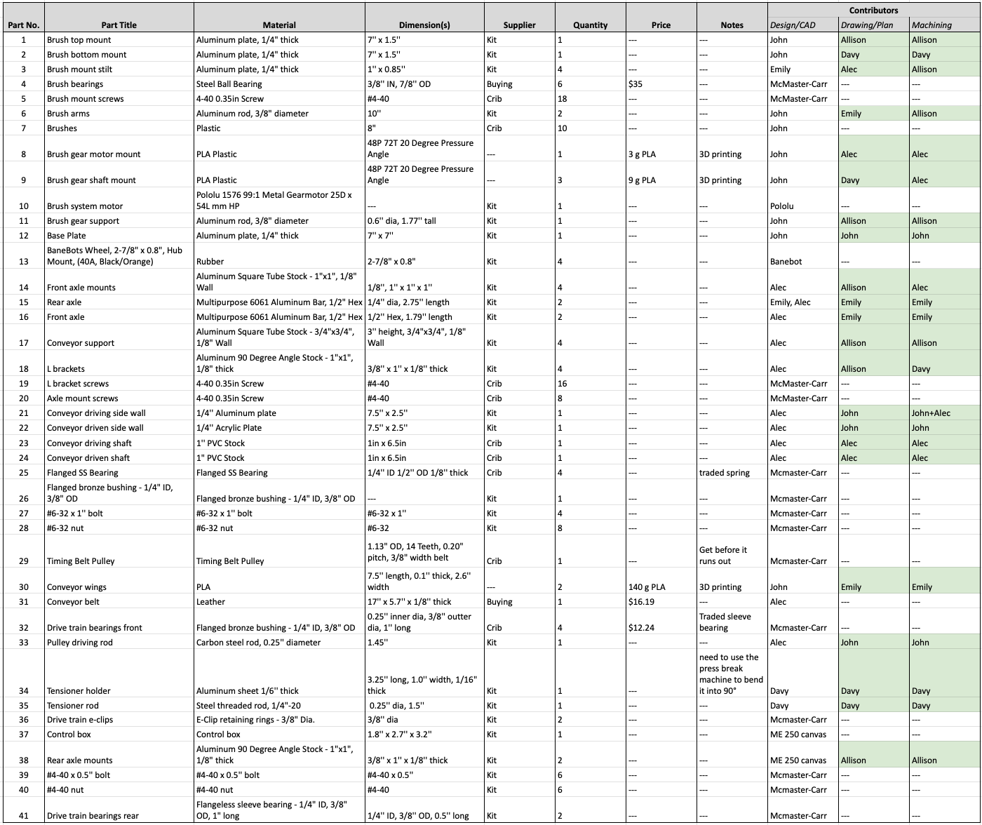
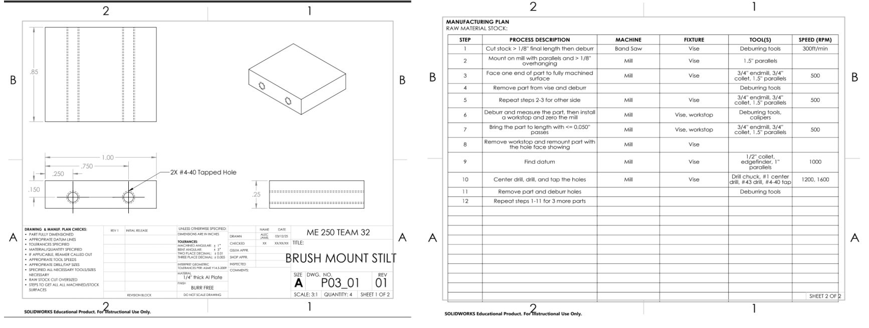
From this BOM, we developed part drawings and manufacturing plans for all the parts we had to manufacture. These were done in SolidWorks using the 2D Drawing feature and looked like this:
We used the mill, lathe, drill press, bandsaw, water jet, 3D printer, and other machining tools to machine all of our components. We put all of our components together until our design came together:
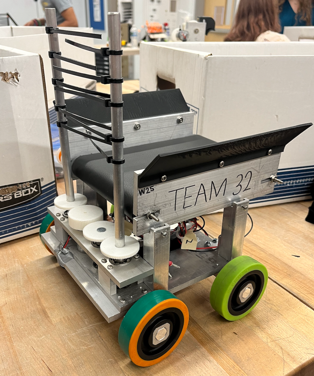
Finally we put our design to the test and it performed well!
Team Members: Allison Chang, Davy Ding, Emily Fokken, John Postiff, Alec Jamil