As a first step of a robotic arm project, I wanted to design and make a speed reducer that would increase the torque output of my NEMA 17 stepper motor while also being compact. That is how I started to learn about cycloidal drives. As a first step, I decided to 3d print a prototype cycloidal drive version, to learn about different design constraints. I first decided that I wanted a 9:1 transmission ratio, so that meant I needed to use 9 lobes on the cycloidal disk, and 10 pins. I started off by designing the cycloidal disk:
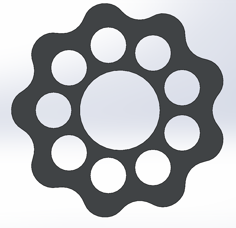
This disk profile was generated using epitrochoid parametric equations along with the following parameters: 45mm pitch diameter, 10mm roller diameter, N = 10 (10 rollers), and 2mm eccentricity. Next, I made holes for the input shaft and the output pins. I also designed another version of the disk, where the holes were 180 degrees out of phase for alignment purposes.
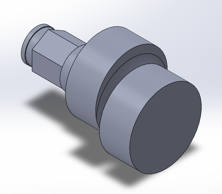
Next I designed an eccentric output shaft so that I could align the two disks exactly 180 degrees out of phase of each other. This is what it ended up looking like:
I also designed a drive housing that would serve the purpose of holding the shaft in place and the rollers for the drive to slide on (the pitch diameter for the rollers was a design parameter that was used to develop the gear profile):
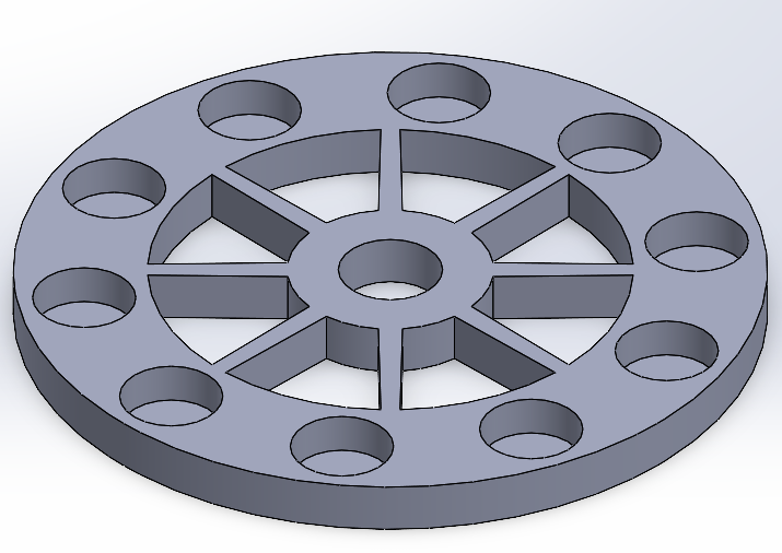
Finally I designed an output shaft object that would help indicate the rotations of the drive output. The diameter of the output pins was chosen carefully to be equal to the output pin hole - 2 * eccentricity for alignment purposes.
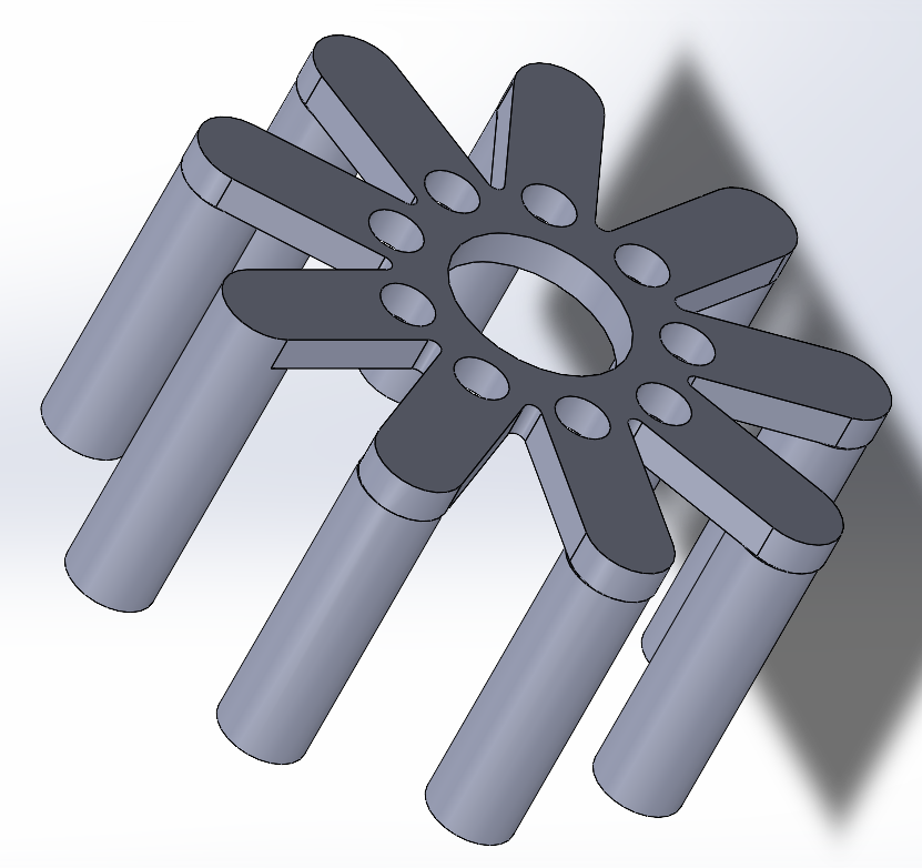
Then, after a few iterations, failed designs, and many SolidWorks motion studies like the one below I was able to assemble a functional cycloidal drive prototype.
It is possible to see that 9 turns of the input crank result in one turn of the output, and this is the desired transmission ratio based on the number of lobes and pins!
After completing a prototype manual design, it was time to design a version that connected to my Nema 17 stepper motor. The cycloidal discs were similar, but I needed a design that minimized friction, maximized rigidity, and still managed to be compact and cheap. After a few iterations, I landed at the following design:
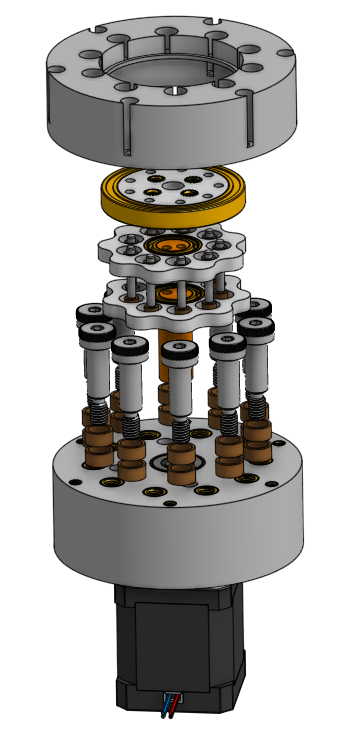
However, the dowel pins serving as the output were replaced with M3 bolts and nuts due to tolerance issues with the stock dowels, and 3d printed spacers were used to constrain the bushings on the shoulder bolts axially.
The drive was made and assembled using a combination of 3d printed parts and other hardware. The stepper motor was driven using a 24V power supply and a DRV8825 driver module. Below are videos of the cycloidal drive in operation, it will be used as the base of a robotic arm project.